Hardware IC PS3 Controller RAM Memory Chip Motherboard

Data Representation


Arithmetic & Logic Unit
  • Does the calculations
  • Everything else in the computer is there to service this unit
  • Handles integers
  • May handle floating point (real) numbers

Data types
  • Represented in binary-coded form
  • Only have 0 & 1 to represent everything
  • Can be classified to these categories:
1. Numbers used in arithmetic computation
2. Letters of the alphabet used in data processing
3. Other discrete symbols used for specific purpose


Alphanumeric Representation
An alphanumeric character set is a set of elements that includes the 10 decimal digits, the 26 letters of the alphabet and a number of special character such as $, +, and =.

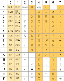
The standard alphanumeric binary code: ASCII (American Standard Code for Information Interchange) uses seven bits to code 128 characters.

Diagram 1: ACSII Code


Alphanumeric Representation
  • Codes must be in binary because registers can only hold binary information. 
Another alphanumeric code used in IBM equipment; EBCDIC (Extended BCD Interchange Code) that uses 8 bits for each character.
  • BCD (Binary Coded Decimal) represents each individual digit of a decimal number as a group of binary bits; the other formats would convert an entire decimal value to its equivalent binary value. *In the 8421 Binary Coded Decimal (BCD) representation each decimal digit is converted to its 4-bit pure binary equivalent. 
Example Decimal to Binary Coded Decimal (BCD)

Number Bases

Different Bases

Decimal --------- (base 10)
Binary  ---------- (base 2)
Octal  ----------- (base 8)
Hexadecimal ---- (base 16)


The Decimal Number Systems
  • The decimal system uses 10 as a base, and the 10 digits available are 0, 1, 2, 3, 4, 5, 6, 7, 8, 9.
  • Depending on its position in the whole number.


For example, the decimal number 9348 represents:


For example, the decimal number 0.258 represents:


For example, the decimal number 7534.448 represents:


The Binary Number Systems

The binary system uses 2 as its base with the digits 0 and 1.

Let’s look at 110100 as an example of a binary number.


Example 1001.101 of a binary number.


In summary, what you need to be able to understand is that the value that is represented by a digit depends on the digit’s position within the number and the base of the numeric system used. With every move of a digit to the right the value represented decrease by a power of the base.


Decimal to Binary Conversion

Integer and fractional parts are handled separately.

Example 19.6875 (base 10) to Binary.


The Octal Number System
  • Base-8 number system.
  • In octal numerals each place is a power with base 8.
  • Uses the digits 0,1,2,3,4,5,6,7.


Example Octal to Decimal: 122 (base 8)


Example Decimal to Octal: 1028 (base 10)


Octal to/from Binary

The binary numbers should be grouped into 3 numbers each as 2 (power 3) = 8.


Example Binary to Octal: 1111101.1001 (base 2)

Example Octal to Binary: 56.3 (base 8)


The Hexadecimal Number System
  • 16 Hexadecimal Digits: 0 – 9, A – F
  • More convenient to use than binary numbers
  • Binary digits are grouped into sets of four bits.

Binary, Decimal, and Hexadecimal Equivalents


Example Binary to Hexadecimal: 1110 1011 0001 0110 1010 0111 1001 0100


Hexadecimal to Decimal

Multiply each digit by its corresponding power of 16


Example Hexadecimal to Decimal: 1234 (base 16)


Decimal to Hexadecimal
  • Repeatedly divide the decimal integer by 16
  • Each remainder is a hex digit in the translated value


Example:

If you don't understand what I was explain. Watch this video:


Instruction Set Architecture


Instruction set architecture is the structure of a computer that a machine language programmer or a compiler must understand to write a correct, timing independent program for that machine.

Elements of a machine instruction:
  • Operation code (opcode)
  • Source operand reference
  • Result operand reference
  • Next instruction reference


Obtain instruction from program storage


Determine required actions and instruction size


Locate and obtain operand data


Compute result value or status


Deposit results in storage for later use


Source and result operands can be in one of four areas:
  • main or virtual memory
  • I/O device
  • processor register
  • Immediate


A simple instruction format represented by a sequence
of bits


Instruction types:
  • data processing: arithmetic and logic instructions
  • data storage: memory instructions
  • data movement: I/O instructions
  • program flow control: test and branch instructions


Number of addresses


Types of operand:

  • Addresses
  • numbers
  • characters
  • logical data


Processor actions for various types of Operations


Addressing Modes and Formats


Immediate Addressing:
  • Simplest form of addressing
  • Operand = address field
  • e.g. ADD 5 - Add 5 to contents of accumulator, 5 is operand
Direct Addressing
  • Address field contains address of operand
  • Effective address (EA) = address field (A)
  • e.g.  ADD A - Add contents of cell A to accumulator, Look in memory at address A for operand
Indirect Addressing
  • Memory cell pointed to by address field contains the address of (pointer to) the operand
  • EA = (A)
  • e.g. ADD (A) - Add contents of cell pointed to by contents of A to accumulator
Register Addressing
  • Similar to direct addressing, the only difference is that the address field refers to a register rather than a main memory address
  • EA = R
Displacement Addressing
  • Combines the capabilities of direct addressing and register indirect addressing
  • EA = A + (R)
Relative Addressing
  • A version of displacement addressing
  • R = Program counter, PC
  • EA = A + (PC)
Base-Register Addressing
  • A holds displacement
  • R holds pointer to base address
  • R may be explicit or implicit
  • e.g. segment registers in 80x86
Indexed Addressing
  • A = base
  • R = displacement
  • EA = A + R
Stack Addressing
  • Operand is (implicitly) on top of stack
  • A stack is a reserved block of locations
  • e.g.  ADD - Pop top two items from stack and add
Instruction Formats


> Define the layout of the bits of an instruction, in terms of its constituent fields


> Must include an opcode and, implicitly or explicitly, indicate the addressing mode for each operand


> For most instruction sets more than one instruction format is used


Allocation of Bits:
  • Number of addressing modes
  • Number of operands
  • Register versus memory
  • Number of register sets
  • Address range
  • Address granularity

Memory System Architecture


For this chapter, i'll explain the purpose and function of Memory System Architecture.

Early computers use the likes of vacuum tubes, switching elements, mercury delay lines and etc. They are very expensive and unreliable.


Then, magnetic cores were introduced in the 1960's. The core represents 1-bit of information. It can be magnetized in two ways ( clockwise and anticlockwise ). Still, it was very expensive and slow.


Since then, all computers have used solid state drives, which is essentially integrated circuits.


Memory capacity are measured in bytes.

Characteristics of Computer Memory System

     Location

           -  Located mainly in three places:
             
                                                            1) CPU
                                                            2) Internal
                                                            3) External

         - Processors require its own local memory in the form of registers.
         - Cache is another form of memory.
         - Internal memory is usually referred to as the main memory.
       - External memory consists of peripheral storage devices that are accessible to the processor via I/O          devices


Capacity


         - The total number of bits that can be stored.
         - Internal memory capacity is typically referred  to as bytes or words. Common word lengths are 8, 16 and 32 bits.
         - External memory capacity are expressed as bytes.

Unit of Transfer


            - For internal memory, unit transfer is equal to the number of lines into and out of the memory module.

            - Internal

                 Governed by data bus width

           - External

                 A block much larger than a word

           - Addressable Unit

                Smallest uniquely addressed location. The relationship between lengths in bits A of an address and number N of addressable units is 2A  = N

Access Methods

          - Sequential
          - Direct
          - Random
          - Associative

Performance

          - Access time
          - Transfer rate
          - Memory cycle time

Physical Types

         - Volatile memory
         - Non-volatile memory
         - Magnetic surface memory
         - Semi-conductor memory
         - Non-erasable memory


Physical Characteristics

         - Volatility
         - Erasable
         - Power consumption


Organization

         - Physical arrangements of bits into words.
         - e.g Interleaved.


Memory Hierachy


Locality of Reference

Semiconductor MemoryTypes


RAM (Random Access Memory)

                - Read/Write
                - Volatile
                - Static or Dynamic

Memory Cell Operation


Dynamic RAM


                     - Bits stored as charge in capacitators
                     - Charges leak
                     - Simpler construction
                     - Less expensive

DRAM Operation

                  - Address line active when bit is written or read
                  

SRAM vs DRAM

 ROM


Types of ROM


Cache


Mapping Function


Associative Mapping


Set Associative Mapping


Cache Replacement


CMOS


Types of External Memory

RAID


Template by GagakHitam
Copyright © 2012 Gagak Hitam and Hishamuddin.